Appendix J – Process of H-point determination
CAA ORS9 Decision No. 1
(see CS 22.785(f))
For the H-point determination, the thigh contact area and the seat level are the two reference areas in a cockpit.
a) Levelling the sailplane
The sailplane should be adjusted with the longitudinal axis horizontal and the wings level
b) Placing and adjusting of the device
With the thighs below the transitional area of seat level and thigh contact area, the device is placed in the centre of the thigh contact area. The device is then slowly pushed down to the thigh contact area until the two lower ends of the thighs touch the seat pan at the same time. This process should ensure that the thighs fully touch the thigh contact area at all times.
When both of the thighs have optimum contact with the thigh contact area or seat level, the device should be adjusted with the use of a spirit level until horizontal at the contact point and fixed in that position.
c) Marking of H-point and determination of optimum location of lap belt anchorage points
When the device is adjusted, the H-point device axis is pushed to one side until a felt-tip pen that is attached to the device touches the side wall of the seat pan. The H-point should be marked at this position. The same procedures should be repeated for the other side.
Continued adjustment of the device should enable the marking of the H-point for each adjusted position.
A rectangle should be drawn around all H-points marked on the side wall of the seat pan, which should be as small as possible. The intersecting point of the rectangle's diagonal shows the "determined H-point".
For the determination of optimum area for the anchorage point of the lap belts, the device is placed on the seat pan in such a way that the H-point of the device corresponds with the "determined H-point" of the seat pan.
The stencil should then be adjusted with the spirit level attached to it allowing the H-point axis to be fixed with the locking device in the connecting part. The area required for the anchorage point of the lap belt can then be identified on the stencil.
H-Point device
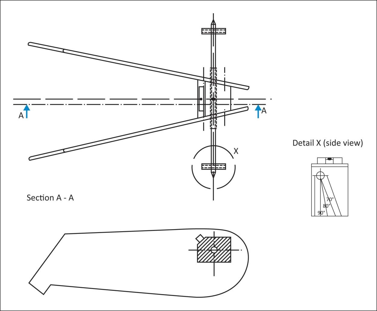
The device is basically composed of the two thighs, the connecting part, and the H-Point axis (see figure 1).

Figure 1
The original constructional drawing of the H-Point device can be ordered by
TÜV Rheinland Kraftfahrt GmbH
Institut für Verkehrssicherheit
Abteilung Luftfahrttechnik
Am Grauen Stein D-51105 Köln