3. SIGNALS FOR AERODROME TRAFFIC
3.1. Light and pyrotechnic signals
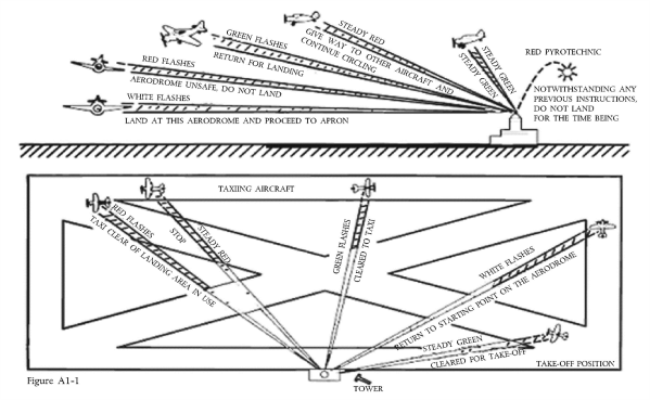
3.1.1. Instructions
| Light | From Aerodrome Control to: | ||
|---|---|---|---|
| Aircraft in flight | Aircraft on the ground | ||
| Steady red | Give way to other aircraft and continue circling | Stop | |
| Series of green flashes | Return for landing1 | Cleared to taxi | |
| Series of red flashes | Aerodrome unsafe, do not land | Taxi clear of landing area in use | |
| Series of white flashes | Land at this aerodrome and proceed to apron2 | Return to starting point on the aerodrome | |
| Directed towards aircraft concerned (see Figure A1-1). |
Steady green | Cleared to land | Cleared for take-off |
| Light | From Aerodrome Control to: | ||
| Red pyrotechnic | Notwithstanding any previous instructions, do not land for the time being | ||
Table AP 1-1
3.1.2. Acknowledgement by an aircraft
(a) When in flight:
(1) during the hours of daylight:
— by rocking the aircraft’s wings, except for the base and final legs of the approach;
(2) during the hours of darkness:
— by flashing on and off twice the aircraft’s landing lights or, if not so equipped, by switching on and off twice its navigation lights.
(b) When on the ground:
(1) during the hours of daylight:
— by moving the aircraft’s ailerons or rudder;
(2) during the hours of darkness:
— by flashing on and off twice the aircraft’s landing lights or, if not so equipped, by switching on and off twice its navigation lights.
3.2. Visual ground signals
3.2.1. Prohibition of landing
3.2.1.1. A horizontal red square panel with yellow diagonals (Figure A1-2) when displayed in a signal area indicates that landings are prohibited and that the prohibition is liable to be prolonged.

Figure A1-2
3.2.2. Need for special precautions while approaching or landing
3.2.2.1. A horizontal red square panel with one yellow diagonal (Figure A1-3) when displayed in a signal area indicates that owing to the bad state of the manoeuvring area, or for any other reason, special precautions must be observed in approaching to land or in landing.

Figure A1-3
3.2.3. Use of runways and taxiways
3.2.3.1. A horizontal white dumb-bell (Figure A1-4) when displayed in a signal area indicates that aircraft are required to land, take off and taxi on runways and taxiways only.

Figure A1-4
3.2.3.2. The same horizontal white dumb-bell as in 3.2.3.1 but with a black bar placed perpendicular to the shaft across each circular portion of the dumb-bell (Figure A1-5) when displayed in a signal area indicates that aircraft are required to land and take off on runways only, but other manoeuvres need not be confined to runways and taxiways.

Figure A1-5
3.2.4. Closed runways or taxiways
3.2.4.1. Crosses of a single contrasting colour, white on runways and yellow on taxiways (Figure A1-6), displayed horizontally on runways and taxiways or parts thereof indicate an area unfit for movement of aircraft.

Figure A1-6
3.2.5. Directions for landing or take-off
3.2.5.1. A horizontal white or orange landing T (Figure A1-7) indicates the direction to be used by aircraft for landing and take-off, which shall be in a direction parallel to the shaft of the T towards the cross arm. When used at night, the landing T shall be either illuminated or outlined in white lights.

Figure A1-7
3.2.5.2. A set of two digits (Figure A1-8) displayed vertically at or near the aerodrome control tower indicates to aircraft on the manoeuvring area the direction for take-off, expressed in units of 10 degrees to the nearest 10 degrees of the magnetic compass.

Figure A1-8
3.2.6. Right-hand traffic
3.2.6.1. When displayed in a signal area, or horizontally at the end of the runway or strip in use, a right-hand arrow of conspicuous colour (Figure A1-9) indicates that turns are to be made to the right before landing and after take-off.

Figure A1-9
3.2.7. Air traffic services reporting office
3.2.7.1. The letter C displayed vertically in black against a yellow background (Figure A1-10) indicates the location of the air traffic services reporting office.

Figure A1-10
3.2.8. Sailplane flights in operation
3.2.8.1. A double white cross displayed horizontally (Figure A1-11) in the signal area indicates that the aerodrome is being used by sailplanes and that sailplane flights are being performed.

Figure A1-11