GM1 CAT.OP.MPA.145(a) Establishment of minimum flight altitudes
CAA ORS9 Decision No. 1
MINIMUM FLIGHT ALTITUDES
(a) The following are examples of some of the methods available for calculating minimum flight altitudes.
(b) KSS formula:
(1) Minimum obstacle clearance altitude (MOCA)
(i) MOCA is the sum of:
(A) the maximum terrain or obstacle elevation, whichever is higher; plus
(B) 1 000 ft for elevation up to and including 6 000 ft; or
(C) 2 000 ft for elevation exceeding 6 000 ft rounded up to the next 100 ft.
(ii) The lowest MOCA to be indicated is 2 000 ft.
(iii) From a VOR station, the corridor width is defined as a borderline starting 5 NM either side of the VOR, diverging 4° from centreline until a width of 20 NM is reached at 70 NM out, thence paralleling the centreline until 140 NM out, thence again diverging 4° until a maximum width of 40 NM is reached at 280 NM out. Thereafter, the width remains constant (see Figure 1).
Figure 1
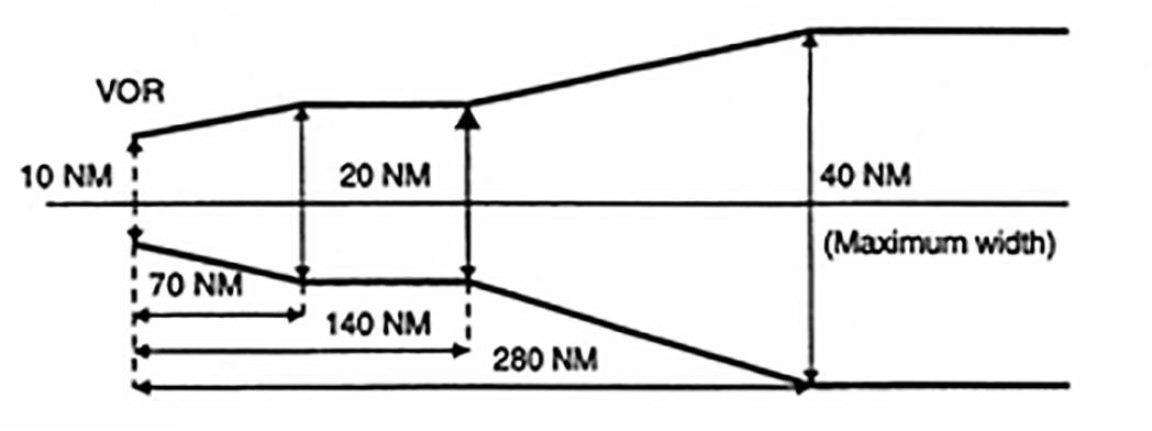
Corridor width from a VOR station
(iv) From a non-directional beacon (NDB), similarly, the corridor width is defined as a borderline starting 5 NM either side of the NDB diverging 7° until a width of 20 NM is reached 40 NM out, thence paralleling the centreline until 80 NM out, thence again diverging 7° until a maximum width of 60 NM is reached 245 NM out. Thereafter, the width remains constant (see Figure 2).
Figure 2
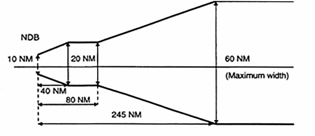
Corridor width from an NDB
(v) MOCA does not cover any overlapping of the corridor.
(2) Minimum off-route altitude (MORA). MORA is calculated for an area bounded by each or every second LAT/LONG square on the route facility chart (RFC)/terminal approach chart (TAC) and is based on a terrain clearance as follows:
(i) terrain with elevation up to 6 000 ft (2 000 m) – 1 000 ft above the highest terrain and obstructions;
(ii) terrain with elevation above 6 000 ft (2 000 m) – 2 000 ft above the highest terrain and obstructions.
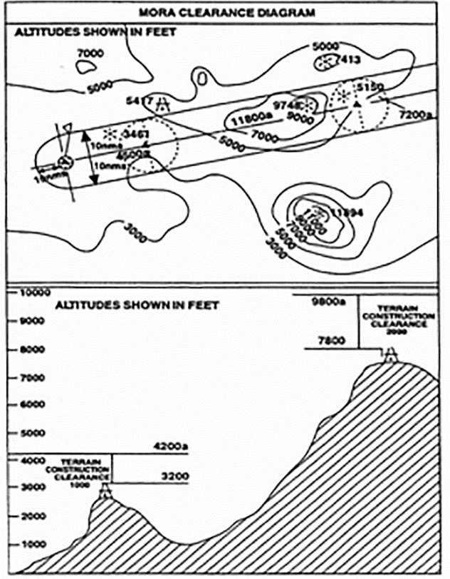
(c) Jeppesen formula (see Figure 3)
(1) MORA is a minimum flight altitude computed by Jeppesen from current operational navigation charts (ONCs) or world aeronautical charts (WACs). Two types of MORAs are charted which are:
(i) route MORAs e.g. 9800a; and
(ii) grid MORAs e.g. 98.
(2) Route MORA values are computed on the basis of an area extending 10 NM to either side of route centreline and including a 10 NM radius beyond the radio fix/reporting point or mileage break defining the route segment.
(3) MORA values clear all terrain and man-made obstacles by 1 000 ft in areas where the highest terrain elevation or obstacles are up to 5 000 ft. A clearance of 2 000 ft is provided above all terrain or obstacles that are 5 001 ft and above.
(4) A grid MORA is an altitude computed by Jeppesen and the values are shown within each grid formed by charted lines of latitude and longitude. Figures are shown in thousands and hundreds of feet (omitting the last two digits so as to avoid chart congestion). Values followed by ± are believed not to exceed the altitudes shown. The same clearance criteria as explained in (c)(3) apply.
Figure 3
Jeppesen formula
(d) ATLAS formula
(1) Minimum en-route altitude (MEA). Calculation of the MEA is based on the elevation of the highest point along the route segment concerned (extending from navigational aid to navigational aid) within a distance on either side of track as specified in Table 1 below:
Table 1
Minimum safe en-route altitude
|
Segment length |
Distance either side of track |
|---|---|
|
Up to 100 NM |
10 NM * |
|
More than 100 NM |
10 % of segment length up to a maximum of 60 NM ** |
*: This distance may be reduced to 5 NM within terminal control areas (TMAs) where, due to the number and type of available navigational aids, a high degree of navigational accuracy is warranted.
**: In exceptional cases, where this calculation results in an operationally impracticable value, an additional special MEA may be calculated based on a distance of not less than 10 NM either side of track. Such special MEA will be shown together with an indication of the actual width of protected airspace.
(2) The MEA is calculated by adding an increment to the elevation specified above as appropriate, following Table 2 below. The resulting value is adjusted to the nearest 100 ft.
Table 2:
Increment added to the elevation *
|
Elevation of highest point |
Increment |
|---|---|
|
Not above 5 000 ft |
1 500 ft |
|
Above 5 000 ft but not above 10 000 ft |
2 000 ft |
|
Above 10 000 ft |
10 % of elevation plus 1 000 ft |
*: For the last route segment ending over the initial approach fix, a reduction to 1 000 ft is permissible within TMAs where, due to the number and type of available navigation aids, a high degree of navigational accuracy is warranted.
(3) Minimum safe grid altitude (MGA). Calculation of the MGA is based on the elevation of the highest point within the respective grid area.
The MGA is calculated by adding an increment to the elevation specified above as appropriate, following Table 3 below. The resulting value is adjusted to the nearest 100 ft.
Table 3
Minimum safe grid altitude
|
Elevation of highest point |
Increment |
|---|---|
|
Not above 5 000 ft |
1 500 ft |
|
Above 5 000 ft but not above 10 000 ft |
2 000 ft |
|
Above 10 000 ft |
10 % of elevation plus 1 000 ft |
(e) Lido formula
(1) Minimum terrain clearance altitude (MTCA)
The MTCA represents an altitude providing terrain and obstacle clearance for all airways/ATS routes, all standard terminal arrival route (STAR) segments up to IAF or equivalent end point and for selected standard instrument departures (SIDs).
The MTCA is calculated by Lido and covers terrain and obstacle clearance relevant for air navigation with the following buffers:
(i) Horizontal:
(A) for SID and STAR procedures 5 NM either side of centre line; and
(B) for airways/ATS routes 10 NM either side of centre line.
(ii) Vertical:
(A) 1 000 ft up to 6 000 ft; and
(B) 2 000 ft above 6 000 ft.
MTCAs are always shown in feet. The lowest indicated MTCA is 3 100 ft.
(2) Minimum grid altitude (MGA)
MGA represents the lowest safe altitude which can be flown off-track. The MGA is calculated by rounding up the elevation of the highest obstruction within the respective grid area to the next 100 ft and adding an increment of
(i) 1 000 ft for terrain or obstructions up to 6 000 ft; and
(ii) 2 000 ft for terrain or obstructions above 6 000 ft.
MGA is shown in hundreds of feet. The lowest indicated MGA is 2 000 ft. This value is also provided for terrain and obstacles that would result in an MGA below 2 000 ft. An exception is over water areas where the MGA can be omitted.