GM1 CAT.POL.H.310(c) & CAT.POL.H.325(c) Take-off and landing
CAA ORS9 Decision No. 1
PROCEDURE FOR CONTINUED OPERATIONS TO HELIDECKS
(a) Factors to be considered when taking off from or landing on a helideck
(1) In order to take account of the considerable number of variables associated with the helideck environment, each take-off and landing may require a slightly different profile. Factors such as helicopter mass and centre of gravity, wind velocity, turbulence, deck size, deck elevation and orientation, obstructions, power margins, platform gas turbine exhaust plumes etc., will influence both the take-off and landing. In particular, for the landing, additional considerations such as the need for a clear go-around flight path, visibility and cloud base, etc. will affect the commander’s decision on the choice of landing profile. Profiles may be modified, taking account of the relevant factors noted above and the characteristics of individual helicopter types.
(b) Performance
(1) To perform the following take-off and landing profiles, adequate all engines operating (AEO) hover performance at the helideck is required. In order to provide a minimum level of performance, data (derived from the AFM AEO out of ground effect (OGE)) should be used to provide the maximum take-off or landing mass. Where a helideck is affected by downdrafts or turbulence or hot gases, or where the take-off or landing profile is obstructed, or the approach or take-off cannot be made into wind, it may be necessary to decrease this take-off or landing mass by using a suitable calculation method. The helicopter mass should not exceed that required by CAT.POL.H.310(a) or CAT.POL.H.325(a).
(For helicopter types no longer supported by the manufacturer, data may be established by the operator, provided it is acceptable to the CAA.)
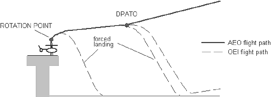
(c) Take-off profile
(1) The take-off should be performed in a dynamic manner ensuring that the helicopter continuously moves vertically from the hover to the rotation point (RP) and thence into forward flight. If the manoeuvre is too dynamic, then there is an increased risk of losing spatial awareness (through loss of visual cues) in the event of a rejected take-off, particularly at night.
(2) If the transition to forward flight is too slow, the helicopter is exposed to an increased risk of contacting the deck edge in the event of an engine failure at or just after the point of cyclic input (RP).
(3) It has been found that the climb to RP is best made between 110 % and 120 % of the power required in the hover. This power offers a rate of climb that assists with deck-edge clearance following engine failure at RP, whilst minimising ballooning following a failure before RP. Individual types will require selection of different values within this range.
Figure 1
Take-off profile
(d) Selection of a lateral visual cue
(1) In order to obtain the maximum performance in the event of an engine failure being recognised at or just after RP, the RP should be at its optimum value, consistent with maintaining the necessary visual cues. If an engine failure is recognised just before RP, the helicopter, if operating at a low mass, may ‘balloon’ a significant height before the reject action has any effect. It is, therefore, important that the pilot flying selects a lateral visual marker and maintains it until the RP is achieved, particularly on decks with few visual cues. In the event of a rejected take-off, the lateral marker will be a vital visual cue in assisting the pilot to carry out a successful landing.
(e) Selection of the rotation point
(1) The optimum RP should be selected to ensure that the take-off path will continue upwards and away from the deck with AEO, but minimising the possibility of hitting the deck edge due to the height loss in the event of an engine failure at or just after RP.
(2) The optimum RP may vary from type to type. Lowering the RP will result in a reduced deck edge clearance in the event of an engine failure being recognised at or just after RP. Raising the RP will result in possible loss of visual cues, or a hard landing in the event of an engine failure just prior to RP.
(f) Pilot reaction times
(1) Pilot reaction time is an important factor affecting deck edge clearance in the event of an engine failure prior to or at RP. Simulation has shown that a delay of 1 second can result in a loss of up to 15 ft in deck edge clearance.
(g) Variation of wind speed
(1) Relative wind is an important parameter in the achieved take-off path following an engine failure; wherever practicable, take-off should be made into wind. Simulation has shown that a 10-kt wind can give an extra 5-ft deck edge clearance compared to a zero wind condition.
(h) Position of the helicopter relative to the deck edge
(1) It is important to position the helicopter as close to the deck edge (including safety nets) as possible whilst maintaining sufficient visual cues, particularly a lateral marker.
(2) The ideal position is normally achieved when the rotor tips are positioned at the forward deck edge. This position minimises the risk of striking the deck edge following recognition of an engine failure at or just after RP. Any take-off heading which causes the helicopter to fly over obstructions below and beyond the deck edge should be avoided if possible. Therefore, the final take-off heading and position will be a compromise between the take-off path for least obstructions, relative wind, turbulence and lateral marker cue considerations.
(i) Actions in the event of an engine failure at or just after RP
(1) Once committed to the continued take-off, it is important, in the event of an engine failure, to rotate the aircraft to the optimum attitude in order to give the best chance of missing the deck edge. The optimum pitch rates and absolute pitch attitudes should be detailed in the profile for the specific type.
(j) Take-off from helidecks that have significant movement
(1) This technique should be used when the helideck movement and any other factors, e.g. insufficient visual cues, makes a successful rejected take-off unlikely. Weight should be reduced to permit an improved one-engine-inoperative capability, as necessary.
(2) The optimum take-off moment is when the helideck is level and at its highest point, e.g. horizontal on top of the swell. Collective pitch should be applied positively and sufficiently to make an immediate transition to climbing forward flight. Because of the lack of a hover, the take-off profile should be planned and briefed prior to lift off from the deck.
(k) Standard landing profile
(1) The approach should be commenced into wind to a point outboard of the helideck. Rotor tip clearance from the helideck edge should be maintained until the aircraft approaches this position at the requisite height (type dependent) with approximately 10 kt of ground- speed and a minimal rate of descent. The aircraft is then flown on a flight path to pass over the deck edge and into a hover over the safe landing area.
Figure 2
Standard landing profile
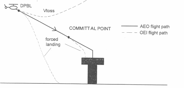
(l) Offset landing profile
(1) If the normal landing profile is impracticable due to obstructions and the prevailing wind velocity, the offset procedure may be used. This should involve flying to a hover position, approximately 90° offset from the landing point, at the appropriate height and maintaining rotor tip clearance from the deck edge. The helicopter should then be flown slowly but positively sideways and down to position in a low hover over the landing point. Normally, the committal point (CP) will be the point at which helicopter begins to transition over the helideck edge.
(m) Training
(1) These techniques should be covered in the training required by Annex III (Part-ORO).